Older charging systems used a relatively simple voltage regulator that maintained output near 14 volts regardless of electrical load. Modern smart alternators communicate with the engine control module over a LIN (Local Interconnect Network) bus. The ECM requests specific charging strategies based on temperature, state of charge, and accessory demand. When the LIN regulator fails or loses communication, output can drop without triggering obvious alternator fault codes.
Symptoms That Mimic Other Components
Drivers report dimming headlights under load, slow cranking after short trips, or a battery warning light that appears briefly then disappears. Because these symptoms overlap with weak batteries and failing starters, unnecessary part replacement is common when LIN communication is not evaluated.
Intermittent failures are particularly difficult because a static voltage test at idle may show normal readings while the regulator fails under thermal stress or high electrical demand.
Voltage Patterns We Monitor
During diagnosis we log charging voltage across multiple operating conditions: cold start, warm idle, elevated RPM, and full accessory load. Healthy LIN-controlled systems typically maintain target voltage within a narrow band defined by the manufacturer — often between 13.5 and 14.8 volts depending on battery state of charge and temperature compensation.
- Sustained output below 13.2 volts under moderate load suggests regulator derating or failure
- Voltage spikes above 15 volts indicate loss of regulation control
- Output that drops when specific accessories activate may point to ECM load management conflicts
- Flatlined output despite RPM increase often confirms mechanical alternator failure rather than LIN issues
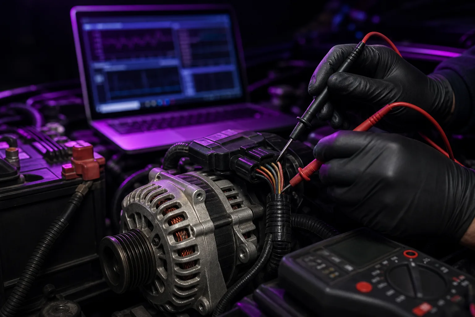
Scope analysis of the LIN bus line during these transitions reveals whether the regulator is receiving and acknowledging commands from the ECM.
Connector Corrosion and Wiring Faults
Before condemning an alternator, we inspect the LIN circuit path from the ECM to the regulator. Corrosion at the alternator harness connector is a frequent cause of intermittent communication loss, especially in vehicles exposed to road salt and moisture.
Pin tension degradation and micro-fractures in the harness near engine mounts produce faults that appear only under vibration. Repairing or replacing the connector and verifying continuity often resolves symptoms without alternator replacement.
Why Replacing the Battery Alone Rarely Fixes It
A new battery temporarily masks undercharging because it starts with full capacity. Within days or weeks, the same regulator fault depletes the replacement battery, leading owners to believe they received a defective unit. Conductance testing confirms battery health independently of charging system performance.
Our workflow separates battery condition assessment from charging system verification. Both must pass before we close a charging-related repair order.
Diagnostic Workflow at paleontolog
Our standard sequence for intermittent charging complaints includes:
- Battery conductance and parasitic draw baseline test
- ECM scan for charging system and LIN communication codes
- Dynamic voltage logging under defined load profiles
- LIN bus signal integrity check at the alternator connector
- Alternator output bench verification if internal regulator replacement is not serviceable
Fleet and Commercial Considerations
Commercial vehicles with high accessory loads — refrigeration units, lift gates, auxiliary lighting — place greater demand on smart charging systems. Regulator faults in these applications often surface during route cycles rather than in the shop bay. Telematics voltage data, when available, helps correlate failures with specific operating conditions.